 English
  Русский
  简体中文
简体中文  Español
  Deutsch
  Français
  Português
  Italiano
  日本語
日本語  한국어
한국어  Türkçe
  Polski
  Nederlands
  العربية
  हिन्दी
  Bahasa Indonesia
  Tiếng Việt
  ไทย
ไทย  বাংলা
বাংলা  اردو
اردو  Kiswahili
  Oʻzbekcha
  አማርኛ
አማርኛ  فارسی
فارسی  繁體中文
繁體中文  Bahasa Melayu
 The optical front end: TOSA, ROSA, BOSA
Đội ngũ của chúng tôi đang thực hiện bản dịch. Bài viết này tạm thời chưa có bản tiếng Việt và đang được hiển thị bằng tiếng Anh.
Strip away the housing, the microcontroller and the EEPROM, and a transceiver is two things: a light source that can be switched fast and a light detector that can read it back. Everything about reach, wavelength, fibre type and cost follows from which source and which detector a module carries. This page introduces the optical front end; the following pages cover lasers, receivers, their evolution by form factor and the chip-on-board way of building them.
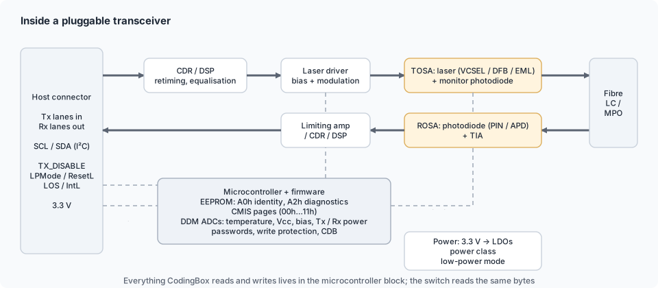
The signal path
 host SerDes ──► laser driver ──► LASER ──► fibre ──► PHOTODIODE ──► TIA ──► LA / CDR ──► host SerDes
(bias + modulation) (current) (voltage) (clean data)- Transmit side. The driver converts the host's electrical bits into a current that switches or modulates the laser; the laser converts current into light at one wavelength; a lens couples that light into the fibre core.
- Receive side. A lens focuses incoming light onto a photodiode, which produces a tiny current; the TIA (trans-impedance amplifier) turns it into a voltage; the LA (limiting amplifier) squares it up to digital levels, or — on PAM4 modules — a linear amplifier feeds an ADC and DSP; the CDR re-times the result.
The sub-assemblies
| Term | Contents | Notes |
|---|---|---|
| TOSA — transmitter optical sub-assembly | laser die, monitor photodiode, sometimes the driver, lens, fibre stub or receptacle; on cooled designs a TEC and thermistor | sets wavelength, launch power, extinction ratio |
| ROSA — receiver optical sub-assembly | photodiode (PIN or APD), TIA, lens, receptacle | sets sensitivity, overload, bandwidth |
| BOSA — bi-directional OSA | TOSA and ROSA behind one WDM filter on one fibre | BiDi and PON modules (1310/1490/1550 nm) |
| Multi-channel OSA | 4- or 8-lane laser and PD arrays with a lens array and MPO/MT ferrule, or an integrated WDM (CWDM4/LR4) mux | parallel and WDM modules |
Traditionally each OSA is a hermetic TO-can (transistor-outline metal package) or a ceramic box; high-volume parallel optics increasingly use bare dies on the board — chip-on-board — and the newest designs integrate modulators and detectors on a silicon photonics chip.
The numbers that matter
| Parameter | Side | Meaning | Where you see it |
|---|---|---|---|
| Wavelength | Tx | centre wavelength of the laser (850, 1310, 1550, CWDM/DWDM channel) | identity bytes; Check transceiver |
| Launch power | Tx | average optical power into the fibre (dBm) | DDM Tx power |
| Extinction ratio | Tx | ratio of "1" to "0" light levels (dB) — higher is easier to detect | spec sheet; not in DDM |
| Chirp / linewidth | Tx | wavelength wobble during modulation — limits reach through dispersion | design choice: DFB vs EML |
| Sensitivity | Rx | minimum power for the target BER (dBm) | low Rx alarm threshold |
| Overload | Rx | maximum power before the receiver saturates | high Rx alarm threshold |
| Responsivity | Rx | current per watt of light (A/W) | design parameter |
| Bandwidth | both | electrical bandwidth — must exceed ~0.7 × symbol rate | rate class |
Link budget = launch power − sensitivity, minus margin; that single subtraction is why a module's laser and photodiode decide its reach class. See CWDM mux/demux & link budget.
Cooled or uncooled
A laser's wavelength drifts with temperature (~0.1 nm/°C for a DFB). Where the wavelength must be precise — DWDM, LAN-WDM LR4, EML-based long reach — the TOSA includes a thermo-electric cooler (TEC) and thermistor. Where 20 nm channel spacing or a single wavelength tolerates drift — SR, LR, CWDM — modules are uncooled, cheaper and lower power. DDM's temperature is the module case; some cooled modules also report laser temperature as an auxiliary monitor (DDM parameters).
What fails, and how it shows
- Laser ageing — bias current climbs to hold power, then output collapses (Failures).
- Receiver degradation — sensitivity worsens; Rx reads fine while errors rise.
- Coupling loss — dirt or misalignment at the receptacle costs decibels on both sides (Link flapping).
- TEC failure on cooled modules — wavelength drifts off the filter passband.
In CodingBox
The optical front end is reported through DDM — Tx power, Tx bias (the laser's health), Rx power (the photodiode's view of the far end) and temperature — which CodingBox reads and trends on the DDM screen. The identity bytes that describe the front end (wavelength, reach, compliance codes) are read and coded in the EEPROM editor; keep them consistent with the real laser and receiver a module carries.
Further reading
- Optical packaging — TO-cans, box TOSAs, lenses, isolators, receptacles and stubs; where alignment costs go.
- WDM inside the module — TFF and AWG multiplexers, BiDi filters, TEC and wavelength lockers; why LR4 is cooled and CWDM4 is not.
- Module electronics — driver, TIA/LA, DSP, controller and power distribution, block by block.
- Modulation & DSP — NRZ vs PAM4, what the DSP does, gearboxes, LPO and coherent modules.
- Controller & firmware — the MCU behind DDM, APC and the memory map; how protection is implemented.
- Manufacturing & testing — from wafer to coded module: alignment, calibration, burn-in, tests.
- Cable internals — what is inside DAC, ACC/AEC and AOC and how the two ends are coded.
Where these components sit in the wider active infrastructure — transceivers, media converters, transponders, amplifiers, ROADMs, PON equipment and monitoring: Active optical infrastructure.