 English
  Русский
  简体中文
简体中文  Español
  Deutsch
  Français
  Português
  Italiano
  日本語
日本語  한국어
한국어  Türkçe
  Polski
  Nederlands
  العربية
  हिन्दी
  Bahasa Indonesia
  Tiếng Việt
  ไทย
ไทย  বাংলা
বাংলা  اردو
اردو  Kiswahili
  Oʻzbekcha
  አማርኛ
አማርኛ  فارسی
فارسی  繁體中文
繁體中文  Bahasa Melayu
 Switch roles and topologies: where each optic ends up
Đội ngũ của chúng tôi đang thực hiện bản dịch. Bài viết này tạm thời chưa có bản tiếng Việt và đang được hiển thị bằng tiếng Anh.
The same 100G module is a cheap DAC in one rack, an SR4 across the room, a LR4 between buildings and a DWDM channel between cities. Which one a port gets is decided by the switch's role in the network and the topology around it. This page maps the classic campus tiers and the data-centre leaf–spine to the optics, distances and counts they imply — so a bill of materials can be read off the design.
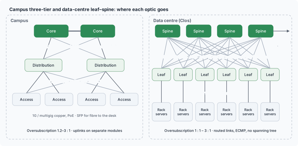
Campus: access, distribution, core
| Tier | Role | Typical ports | Downlinks | Uplinks and optics |
|---|---|---|---|---|
| Access | connects end devices | 24–48 × RJ45 (1G/mGig, PoE) + 2–4 SFP+/SFP28 uplinks | copper | 10G/25G SR (in-building MMF), LR (between buildings), sometimes 1G LX |
| Distribution / aggregation | aggregates access switches per building or floor group | 24–48 × SFP+/SFP28, 4–8 × QSFP28 | 10G/25G SR/LR | 40G/100G SR4/LR4 to core; CWDM/DWDM if fibre is scarce |
| Core | interconnects distribution, routes | QSFP28/QSFP-DD | 100G/400G | LR4/FR4/ER4 between sites; CWDM or DWDM over leased fibre |
| Collapsed core | small sites: distribution + core in one | mixed | — | — |
Campus distances are metres to a few kilometres: SR on OM3/OM4 inside buildings, LR/LX on single-mode between them; the reach classes in PMD reference.
Data centre: leaf–spine (Clos)
| Role | Also called | Ports | Downlinks | Uplinks |
|---|---|---|---|---|
| Leaf | ToR (top of rack), access | 48 × SFP28/SFP56 + 8 × QSFP28/QSFP-DD, or 32 × QSFP-DD | servers: 25G/50G/100G — DAC in rack (≤ 3 m), AOC/SR to adjacent racks | to every spine: 100G/400G SR4/DR4/AOC (≤ 100 m) |
| Spine | aggregation, fabric | 32–64 × QSFP28/QSFP-DD/OSFP | leaves | to super-spine or border: DR4/FR4 (500 m–2 km) |
| Super-spine / core | pod interconnect | high-radix 400G/800G | spines | DR/FR within the campus; ZR/ZR+ for DCI (Coherent) |
| Border leaf | edge to WAN/internet | mixed | — | LR/ER/CWDM/DWDM to carriers |
| Management | out-of-band | 1G RJ45/SFP | BMCs, consoles | 1G/10G LR to the OOB core |
Rules of thumb: leaf–spine links are all the same speed and FEC; oversubscription (downlink capacity ÷ uplink capacity) of 3:1 is common for general compute, 1:1 for AI and storage (GPU fabrics).
Rail-optimised AI fabrics
GPU nodes connect each NIC to a different leaf, so most server links leave the rack — AOC and optics instead of DAC — and the cable count per GPU is one per tier (Cabling an AI cluster).
Storage and SAN
Fibre Channel switches form their own fabric (edge–core or core–edge–core) with 16/32/64GFC SW optics in a room and LW between rooms; Ethernet storage rides the leaf–spine with lossless classes (SAN design, Lossless Ethernet).
Distance → optic
| Segment | Distance | Medium | Optic |
|---|---|---|---|
| Server to ToR | ≤ 3 m | copper | DAC (Cable internals) |
| Server to end-of-row leaf | 3–30 m | AOC or MMF | AOC, SR |
| Leaf to spine, same hall | 10–100 m | OM4 or SMF | SR4/SR8, DR4/DR8 |
| Between halls / buildings | 100 m – 2 km | SMF | DR, FR4, LR/LX |
| Campus / metro | 2–40 km | SMF | LR, ER, CWDM, 4WDM |
| Regional DCI | 40–120 km | SMF, amplified | ZR/ZR+, DWDM transponders |
| Long haul | > 120 km | SMF, amplified | DWDM line systems (Network design & OTN) |
Fibre-scarce paths use CWDM or DWDM to multiply capacity per strand; single-fibre BiDi where only one strand exists.
Counting optics from a design
Example: one pod of 16 racks, 32 servers per rack, 2 × 25G per server, 4 spines.
| Item | Count |
|---|---|
| Server links (2 × 25G × 32 × 16) | 1 024 DAC |
| Leaf uplinks (16 leaves × 4 spines × 2 × 100G) | 128 links → 256 QSFP28 SR4/DR4 + 128 MPO trunks |
| Spine to super-spine (4 spines × 8 × 100G) | 32 links → 64 modules |
| Border + OOB | 8–16 LR modules, 48 1G |
| Spares (5 %) | ~20 |
Multiply by two for the second fabric if the design is dual-plane.
Roles and policy
Role also decides how strict the platform is about optics: carrier and SAN gear tends to enforce OEM branding; data-centre leaf–spine on merchant silicon is often permissive; campus access varies by vendor (How each NOS validates a module, Vendor lock).
In CodingBox
A role-based bill of materials is a list of PMDs and part numbers; CodingBox verifies each delivered module against it (type, reach, wavelength, PN) and codes identities where the design calls for OEM-compatible modules (Check transceiver, Code database).
Turning a design into a purchase and a working rack — selection criteria, optics bill of materials, commissioning checklist and acceptance test: Selecting & commissioning; the L2/L3 mechanics behind these topologies: Forwarding basics.
The cabling under these topologies — structured cabling hierarchy, data-centre patterns (EoR, MoR, ToR, trunks and cassettes), fibre-count planning: Fibre network topologies.