 English
  Русский
  简体中文
简体中文  Español
  Deutsch
  Français
  Português
  Italiano
  日本語
日本語  한국어
한국어  Türkçe
  Polski
  Nederlands
  العربية
  हिन्दी
  Bahasa Indonesia
  Tiếng Việt
  ไทย
ไทย  বাংলা
বাংলা  اردو
اردو  Kiswahili
  Oʻzbekcha
  አማርኛ
አማርኛ  فارسی
فارسی  繁體中文
繁體中文  Bahasa Melayu
 Antara muka bebas media: sisi elektrik port
Pasukan kami sedang menyiapkan terjemahan. Artikel ini buat sementara waktu belum tersedia dalam bahasa Melayu dan dipaparkan dalam bahasa Inggeris.
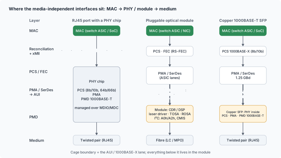
Between the Ethernet MAC inside a switch ASIC or NIC controller and the medium — copper pair, fibre, backplane — sits a standardised electrical interface. IEEE calls the family media-independent interfaces (MII): the MAC does not care whether the far side is a copper PHY, an SFP cage or a 400G module, as long as it speaks the agreed interface. Every generation of Ethernet added one: MII and RMII for 10/100, GMII/RGMII/SGMII for gigabit, XGMII/XAUI/XFI/SFI for 10G, and the AUI family (CAUI-4, 400GAUI-8, 800GAUI-8) for everything since. This section explains them from the transceiver's point of view — what arrives at the cage, what a copper SFP has to emulate, and why a port "in the wrong mode" refuses a perfectly good module.
Why the split exists
| Layer | Lives in | Interface to the next layer |
|---|---|---|
| MAC (framing, addresses) | switch ASIC, NIC controller, SoC | reconciliation sublayer → xMII |
| PCS (coding: 8b/10b, 64b/66b, FEC) | ASIC/controller for pluggables; PHY chip for copper | PMA |
| PMA / SerDes | ASIC SerDes or PHY | AUI lanes to the module or medium |
| PMD (laser, copper driver) | transceiver module or PHY chip | fibre / cable |
For pluggable optics the PCS and SerDes stay in the host; the module receives serial lanes (SFI, CAUI-4, 400GAUI-8) and converts to light. For copper, a PHY chip does PCS+PMA+PMD and talks to the MAC over a parallel (RGMII) or serial (SGMII) interface. A copper SFP puts that PHY inside the module, so the cage must carry SGMII or 1000BASE-X to it (SGMII & serial gigabit).
The ladder
| Interface | Rate | Form | Signals | Reach | Defined by | Typical place |
|---|---|---|---|---|---|---|
| MII | 10/100 | 4-bit parallel @ 2.5/25 MHz | 16–18 | cm | IEEE 802.3 Cl. 22 | legacy MAC ↔ PHY |
| RMII | 10/100 | 2-bit @ 50 MHz | 7–9 | cm | RMII Consortium | embedded SoC ↔ PHY |
| SMII / SS-SMII | 10/100 | 1-bit @ 125 MHz | 2–3 per port | cm | Cisco | multi-port PHYs |
| GMII | 1G (+10/100) | 8-bit @ 125 MHz | 24+ | cm | Cl. 35 | MAC ↔ PHY, mostly on-chip today |
| RGMII | 1G (+10/100) | 4-bit DDR @ 125 MHz | 12 | ≤ 10–15 cm | HP/Marvell RGMII v1.3/2.0 | SoC ↔ copper PHY on small switches/routers |
| TBI / RTBI | 1G | 10-bit @ 125 MHz | 20+ | cm | Cl. 36 | MAC ↔ external SerDes (legacy) |
| 1000BASE-X (SerDes) | 1G | 1 lane 1.25 GBd, 8b/10b | 2 diff pairs | 50 cm+ | Cl. 36/37 | what an SFP cage carries at 1G |
| SGMII | 10/100/1000 | 1 lane 1.25 GBd, 8b/10b | 2 pairs (+ clocks) | 50 cm+ | Cisco SGMII v1.8 | MAC ↔ copper PHY; MAC ↔ copper SFP |
| 2500BASE-X | 2.5G | 1.25 × SGMII/1000BASE-X rate: 3.125 GBd | 2 pairs | 50 cm | de facto | 2.5G SFP, PON sticks |
| QSGMII | 4 × 1G | 1 lane 5 GBd | 2 pairs | 50 cm | Cisco | ASIC ↔ quad copper PHY |
| USXGMII | 10M–10G | 1 lane 10.3125 GBd, 64b/66b | 2 pairs | 30 cm | Cisco/Marvell | ASIC ↔ mGig PHY; 10GBASE-T SFP+ |
| XGMII | 10G | 32-bit DDR @ 156.25 MHz | 74 | < 7 cm | Cl. 46 | on-chip |
| XAUI | 10G | 4 × 3.125 GBd, 8b/10b | 8 pairs | 50 cm | Cl. 47 | XENPAK/X2 modules, legacy PHYs |
| XFI / SFI | 10G | 1 × 10.3125 GBd, 64b/66b | 2 pairs | 20–30 cm | XFP MSA / SFF-8431 | XFP / SFP+ cage |
| 10GBASE-KR | 10G | 1 × 10.3125 GBd | 2 pairs | 1 m backplane | Cl. 72 | backplanes, 10GBASE-T PHYs |
| 25GAUI | 25G | 1 × 25.78 GBd NRZ | 2 pairs | C2M | Annex 109A/B | SFP28 cage |
| XLAUI / CAUI-10 | 40G / 100G | 4 / 10 × 10.3125 GBd | 8 / 20 pairs | C2C/C2M | Annex 83A/B | QSFP+ / CFP, CXP |
| CAUI-4 | 100G | 4 × 25.78 GBd NRZ | 8 pairs | C2M | Annex 83D/E | QSFP28 cage |
| 50GAUI-2 / -1 | 50G | 2 × 26.5625 NRZ / 1 × 26.5625 GBd PAM4 | 4 / 2 pairs | C2M | Annex 135B–E | SFP56 |
| 100GAUI-4 / -2 / -1 | 100G | 4 × NRZ / 2 × 53 GBd PAM4 / 1 × 10⁶ GBd PAM4 | — | C2M | Annex 135D–G, 120G | QSFP28 (PAM4 variants), QSFP112 |
| 200GAUI-8 / -4 / -2 | 200G | 8 × 26.5 PAM4 / 4 × 53 / 2 × 10⁶ | — | C2M | Annex 120C–G | QSFP56, QSFP112 |
| 400GAUI-16 / -8 / -4 | 400G | 16 × 25 NRZ / 8 × 53 PAM4 / 4 × 10⁶ PAM4 | — | C2M | Annex 120B–G | CFP8 / QSFP-DD, OSFP / QSFP112, OSFP |
| 800GAUI-8 / -4 | 800G | 8 × 10⁶ PAM4 / 4 × 212 PAM4 | — | C2M | 802.3df / dj | OSFP, QSFP-DD800 / OSFP224, OSFP-XD |
Details: MII, RMII, GMII, RGMII, SGMII, 1000BASE-X, QSGMII, USXGMII, XGMII, XAUI, SFI and the AUI family.
Where each one sits
| Device | MAC → … | … → medium |
|---|---|---|
| 48-port 1G copper switch | ASIC → QSGMII → quad PHYs | PHYs → RJ45 |
| Small router / SoC board | SoC → RGMII or SGMII → PHY | PHY → RJ45; or SoC → 1000BASE-X/SGMII → SFP cage |
| 10G/25G switch or NIC SFP+/SFP28 port | ASIC SerDes → SFI / 25GAUI → cage | module → fibre or DAC |
| 100G QSFP28 port | ASIC → CAUI-4 (4 × 25G) → cage | module → 4 λ or 4 fibres |
| 400G QSFP-DD / OSFP port | ASIC → 400GAUI-8 (8 × 50G PAM4) → cage | module gearbox → 4 × 100G optical |
| 800G OSFP port | ASIC → 800GAUI-8 (8 × 100G PAM4) → cage | module → 8 × 100G (DR8) or 4 × 200G |
| Copper 1000BASE-T SFP | host 1000BASE-X or SGMII → module's PHY | PHY → RJ45 |
| 10GBASE-T SFP+ | host SFI (10GBASE-R) → module's PHY (USXGMII-class) | PHY → RJ45 |
| Multigig RJ45 switch port | ASIC → USXGMII → mGig PHY | 2.5/5/10GBASE-T |
Management of PHYs vs modules
| Copper PHY chip | Pluggable module | |
|---|---|---|
| Bus | MDIO/MDC (Clause 22: 5-bit address, 32 × 16-bit registers; Clause 45: device/register pairs for 10G+) | I²C two-wire (A0h/A2h, CMIS pages) (Two-wire interface) |
| Link status | PHY status register (reg 1), in-band on RGMII/SGMII | LOS/LOL pins and flags, DDM |
| Linux tools | mii-tool, phytool, ethtool (PHY driver) | ethtool -m, i2c-dev (NIC tools) |
| Copper SFP oddity | the PHY inside the module is reachable over I²C at a second address (e.g. 0xAC on Marvell 88E1111-based modules) or via vendor pages — MDIO tunnelled | — |
Why it matters for transceiver work
- Mode of the cage. A 1G SFP port can be in 1000BASE-X or SGMII mode; a copper SFP behaves differently in each, and 10/100 clients only work in SGMII (or with a module that hides the difference) (SGMII & serial gigabit).
- Rate and coding. The module must accept the host's lane rate and coding: SFI at 10.3125 GBd, CAUI-4 at 25.78, 400GAUI-8 PAM4 — this is what compliance codes and CMIS applications advertise (Compliance codes).
- Who retimes. SFP+ modules are often linear/limiting with host equalisation; 25G+ modules carry CDRs; PAM4 modules carry DSPs; LPO modules are linear again and depend on the host SerDes (CDR, DSP & LPO).
- Electrical ≠ optical lanes. 400G-FR4 takes 8 electrical lanes and emits 4 wavelengths; the gearbox is in the module (XGMII, XAUI and the AUI family).
- Linux picks the interface from the EEPROM. The kernel's SFP layer reads bytes 3–10, 12 and 36 to decide between 1000BASE-X, SGMII, 2500BASE-X, 10GBASE-R — a wrong compliance byte makes a good module link in the wrong mode (Memory map).
Further reading
- MII, RMII, GMII, RGMII — the parallel interfaces: pins, clocks, RGMII delay modes, in-band status, PHY management over MDIO, typical faults.
- SGMII, 1000BASE-X, QSGMII, USXGMII — serial interfaces to PHYs and SFP cages: auto-negotiation differences, copper SFPs, 100BASE-FX, 2.5G, multigig, how Linux chooses the mode.
- XGMII, XAUI, XFI/SFI and the AUI family — from 10G to 800G: lane counts, C2C vs C2M, compliance points, OIF CEI mapping, electrical-to-optical lane mapping, retimed vs linear modules.
In CodingBox
The bytes CodingBox shows are the module's statement of which host interfaces it supports: compliance codes (1000BASE-T → SGMII/1000BASE-X capable copper), nominal bit rate, encoding byte (8b/10b vs 64b/66b vs PAM4), CDR bits and CMIS host-interface IDs. Editing them changes which interface the host will try (Check transceiver, Compliance codes).